How to Build a 4511 BCD to 7 Segment Decoder Circuit
In this circuit, we will build a BCD to 7 segment display decoder circuit using the 4511 chip.
A BCD to 7 segment decoder circuit is a circuit that intakes a binary value and displays the equivalent decimal value on the 7 segment display.
Using binary coded decimal (BCD), we can display any numerical digit on the 7 segment display from 0 to 9- using only 4 pins. Otherwise, without this chip, to display all the decimal digits (0-9), you would have to use 7 pins; so it saves us 3 pins.
How the 4511 BCD to 7 segment display decoder works is it has 4 pins that intake a binary value. Each of these 4 pins can hold a 0 (LOW) or a 1 (HIGH). These data pins are referred to in the datasheet as D, B, C, and A. We can choose what digit we want to display by inputting the equivalent binary value into these data pins. For example, if we want to display 6 on the 7 segment display, we input the value 0110 into the DBCA data pins. The binary value 0110 is the equivalent of the decimal value of 6. This is why it's called binary coded decimal. With the binary value input, the equivalent decimal value of that binary number is displayed on the 7 segment display. Otherwise, you would have to know which pins on the 7 segment display to turn on or off, making it much more complicated. This chip saves us a lot of work for that reason.
In this circuit, we will start the 4511 BCD to 7 segment display decoder with the most basic circuit. We will connect this chip by itself to pushbuttons. Using the pushbuttons, you can manually see how depending on which pushbuttons we press, how the output changes in response. So we can see which combinations of pushbuttons turned on displays which decimal values.
Below, we will also explain how BCD to 7 segment display decoders work in great detail, specifically
the 4511 chip.
Components
- 4511 BCD to 7 Segment Display Decoder
- 7 segment display
- 4 1KΩ resistors
- 7 470Ω resistors
- 4 pushbuttons
The 4511 BCD to 7 segment display decoder can be gotten very cheaply for under $1 on ebay.
The 4511 chip takes in a binary value and displays the equivalent decimal value on the 7 segment display.
The 4511 is a 16-pin chip. The pinout of the 4511 is shown below.
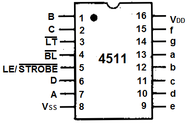
To power the chip, VDD, pin 16 to 5V and VSS, pin 8, connects to ground. The 4511 chip is capable of handling up to 20V.
The 4 input data pins, which control the digit which is shown on the 7-segment LED display, are D, C, B, and A which are pins 6, 2, 1, and 7, respectively. These 4 data pins are fed binary values. Connecting a pin to VCC puts the pin in a HIGH state or value. Connecting a pin to ground or 0V puts the pin in a LOW state or value. This is how we adjust the value of these data pins. There are 4 data pins hold a binary value. The decimal equivalent of the binary value that it holds will be displayed on the 7 segment display. So, for example, if we want to show the decimal number 5, we give a value of 0101 to the DCBA data pins.
Pin 3 is the
Pin 4 is the
The LE/
Lastly, the 8 output pins are labeled a, b, c, d, e, f g, which are pins 12, 12, 11, 10, 9, 15, and 14. These are the pins we attach to each of the corresponding pins on the 7 segment LED display. For example, a on the 4511 matches to a on the 7 segment LED display, b matches with b, etc.
The decimal digit that the 7 segment display shows out depends on the binary value fed into the 4 input data pins DBCA.
The table below summarizes the binary input values to the decimal digit shown on the 7 segment display.
| Binary Coded Decimal Chart | |||||
| Decimal Number | Binary Word | B8 | B4 | B2 | B1 |
| 0 | 0000 | Low | Low | Low | Low |
| 1 | 0001 | Low | Low | Low | High |
| 2 | 0010 | Low | Low | High | Low |
| 3 | 0011 | Low | Low | High | High |
| 4 | 0100 | Low | High | Low | Low |
| 5 | 0101 | Low | High | Low | High |
| 6 | 0110 | Low | High | High | Low |
| 7 | 0111 | Low | High | High | High |
| 8 | 1000 | High | Low | Low | Low |
| 9 | 1001 | High | Low | Low | High |
You can see based on this chart why it's a binary coded decimal system.
If we input a binary value into the data pins, we get the corresponding decimal digit equivalent shown out on the 7 segment display.
So, for example, if we input 0000 into the data pins, we get the number 0.
4511 BCD to 7 Segment Display Decoder Circuit
The 4511 BCD to 7 segment display decoder circuit we will build is shown below.
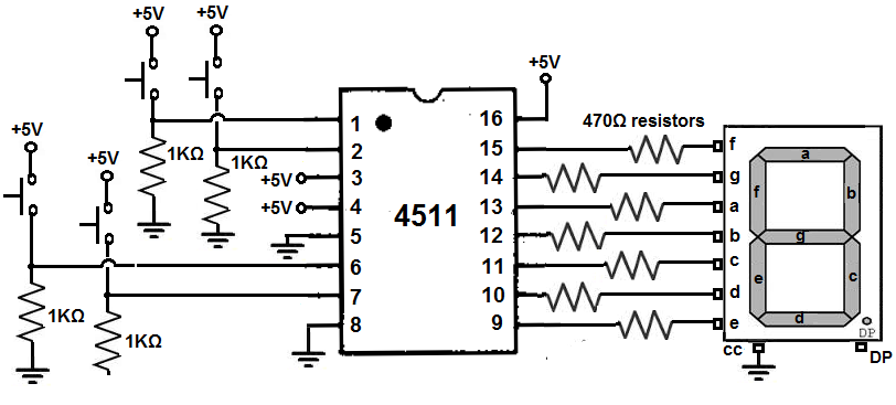
First, to power the 4511 chip, we connect VDD, pin 16, to +5V and VSS, pin 8, to ground. This establishes sufficient power to the 4511 chip.
The
The
The LE/
The 4 data pins are D, B, C, and A. These pins are all connected to pull-down resistors. Without the pushbuttons being pressed, the pins are all in a LOW state. If the pushbuttons are pressed, they go to a HIGH state. Depending on the combination of pushbuttons being pressed determines the decimal digit that will be shown on the 7 segment LED display; this is summarized in the table above.
To each of the output pins, a through g, we connect an LED with a 470Ω current-limiting resistor.
How the Circuit Works
The circuit works directly through the control of the 4 pushbuttons which control the binary value we feed into the data input pins.
Being that they are all connected to pull-down resistors, they are all initially LOW when unpressed. So the 7 segment LED display will show a 0 initially.
The combination of pushbuttons pressed and unpressed determines the decimal digits, according to the binary value. The equivalent decimal value of the binary value we feed into the data input pins will be shown.
We can show the digits 0 through 9. We cannot show any other digits on the 7 segment display. So the highest value we can feed into is 1001, which is 9 in decimal. Any value above this amount cannot be shown on the 7 segment LED display.
So if we want to show a 4, we pressed down on pushbutton C while having all the other pushbuttons unpressed. You should now see a 4 on the 7 segment LED display.
The 4511 really makes it much simpler to work with single 7 segment LED displays.
To see how to make a 7 segment display count up from 0 to 9 or count down from 9 to 0 automatically without any manual pushbutton intervention, we can
connect a binary up/down counter to this circuit. To see how to build this circuit, see
How to Build a Binary Up/Down Counter with a 4516 Chip
Related Resources
How to Vary the Brightness of an LED
How to Build an LED Driver Circuit
How to Build an LED Flasher Circuit