How to Build an Ohmmeter Using an Arduino
In this project, we will show how you can build an ohmmeter using an arduino.
An ohmmeter is a device that can measure resistance.
Most of the times now, ohmmeters aren't standalone devices but appear as one of type of measuring device amongst many in a multimeter. An advanced multimeter, today, would have an ohmmeter, voltmeter, ammeter, capacitance meter, continuity tester, and possibly a temperature sensor. For this circuit, we are only going to build an ohmmeter, as to measure resistance.
Using the correct hardware interface and uploaded code, we can turn the arduino into a device that can measure
resistance.
Parts Needed
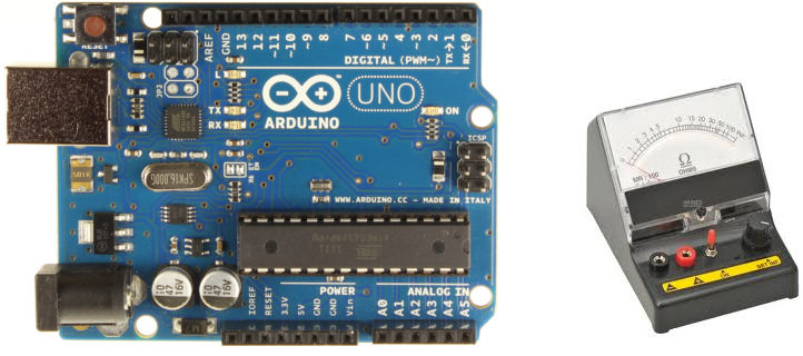
- Arduino
- 1KΩ resistor
- Resistor (whose value you want to measure)
These are all the parts which you will need. The circuit is very basic, as you will see below.
Circuit Schematic
The circuit schematic for the ohmmeter using an arduino is shown below.
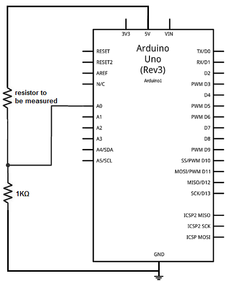
How this ohmmeter circuit works is that the 2 resistors in series forms a voltage divider circuit. One end of the resistor pair is hooked up to 5V and the other end is hooked up to ground. The 5 volts that the arduino provides gets divided up between the 2 resistors, depending on the value of the 2 resistors. The resistor which holds the greater resistance gets more of the voltage, according to ohm's law formula, V=IR. The voltage that falls across a component is directly proportional to the amount of resistance it contains. Using this principle, we can set up a mathematical model to determine the resistance, based on the voltage division.
You will see in the code below how this works.
Code
//This code will display the voltage that drops across the unknown resistor
//along with its resistance
int analogPin= 0;
int raw= 0;
int Vin= 5;
float Vout= 0;
float R1= 1000;
float R2= 0;
float buffer= 0;
void setup()
{
Serial.begin(9600);
}
void loop()
{
raw= analogRead(analogPin);
if(raw)
{
buffer= raw * Vin;
Vout= (buffer)/1024.0;
buffer= (Vin/Vout) -1;
R2= R1 * buffer;
Serial.print("Vout: ");
Serial.println(Vout);
Serial.print("R2: ");
Serial.println(R2);
delay(1000);
}
}
We create a variable called analogPin and assign it to 0. This is because the voltage value we are going to read is connected to analogPin A0. This voltage represents the voltage value which falls across the resistor value we are measuring.
Next we create a variable named raw, which we will use to read in the analog voltage value. This later in our code gets assigned to the analogRead() function. This value which will be placed into the raw variable can be between 0 and 1023. 0 would represent 0 volts falls across the unknown resistor. And a value of 1023 would mean that practically all 5 volts falls across the unknown resistor. Being that we are using a reference resistor of 1KΩ, a very small resistor such as 1Ω may make the A0 pin register a value of 0. And a very large resistor, such as 1MΩ would make it read a value of 1023. These are just examples to give you a feel for how the ohmmeter would work with a 1KΩ resistor as its reference resistor.
The next variable, Vin, is assigned to 5 because 5V is being supplied by the arduino to the resistive voltage divider circuit.
The next variable, Vout, is assigned initially to 0. Vout represents the divided voltage that falls across the unknown resistor.
The next variable, R1, represents the reference resistor. In our case, we are using a 1KΩ resistor as our reference, so we set it equal to 1000. If you are going to change the reference resistor to another value, for reasons explained below, you will need to change it in hardware and in software.
The variable, R2, represents the unknown resistor. It is initially set to 0 but our algorithm in our code will help us determine what value it is after the voltage that falls across it has been measured.
The next variable, buffer, is just for a placeholder for intermediate calculations.
The last block of code is our algorithm to calculating and displaying the unknown resistor value.
If you work with resistors whose values are going to be much smaller than 1KΩ or much larger than 1KΩ, then you would have to change the reference
resistor to a value near the range of the resistors you are going to test. If you are testing very small resistances such as in the range of 1-100Ω, it would be
best to make the reference resistor 100Ω. This way, you would get more accurate readings. Remember, this is a voltage divider circuit. If the 2 resistors are too
far apart from each other, you are going to get far-range, all-or-none readings. For example, if the reference resistor is 1KΩ and the unknown resistor is 1, this
means that 5V(1Ω/1001Ω)= 0.00499V falls across the 1Ω resistorand 0.995V falls across the 1KΩ resistor. The 0.00499V is so small of a number
that it doesn't give much weight in the calculations. Instead if you use a 10Ω resistor as the voltage divider, then 5V(1Ω/10Ω)= 0.5V falls
across the 1Ω resistor. This will give more weight and accuracy in the calculations. Thus, it will be able to tell with greater accuracy
what value this unknown resistor is. This is why you should have a reference resistor in the range of the resistor values you will be testing.
This is how manual ohmmeters work. These are multimeters that have an ohmmeter that you have to manually select the range. This is not
an autoranging ohmmeter.
Related Resources
How to Drive a 7 Segment LED Display with an Arduno
How to Build a Dark-activated Light Circuit
How to Build a Hall Effect Sensor Circuit
How to Build a Touch Sensor Circuit
How to Build an Accelerometer Circuit
How to Build a Motion Detector Circuit
How to Build a Motion Detector Alarm Circuit