
How To Test a Voltage Regulator
A voltage regulator is a device that takes in an input voltage and regulates it down to the voltage that it is rated for.
Being that a voltage regulator passes out a regulated output voltage, the only test we must do to check a voltage regulator is a voltage test.
We check the voltage input into the voltage regulator and the voltage output from the regulator.
If we read at the input pin the voltage which we feed into the regulator and read at the output pin the output voltage which the regulator is rated for, then we know that the voltage regulator is good. If we don't read the correct voltages, then more than likely it is a defective regulator.
So we'll now go through specifically how to test a voltage regulator.
Before we get into how to read the voltages with a multimeter, first we'll go over the pinout of a voltage regulator, so that you'll know which pins to read voltages from.
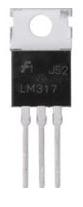
As an example, we'll use the popular voltage regulator, the LM7805. Below is the pinout of the LM7805 voltage
regulator:
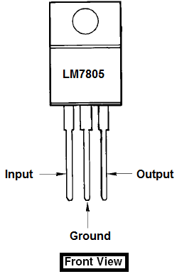
The input voltage that needs to be regulated down goes into pin 1 (Input). The ground pin is pin 2. And
the regulated output voltage comes out from pin 3 (Output).
Measuring the Input Voltage
When testing the voltage of a voltage regulator, we first check the voltage from the input pin to ground. This is to make sure that voltage is, in fact, being supplied to the regulator. If the regulator isn't receiving sufficient voltage, of course it will not be able to output its rated regulated voltage. This is why we do this test.
To test the voltage going into the voltage regulator, we take a multimeter and place it in the DC voltage setting.
The DC voltage setting is the setting of the multimeter that has the following symbol or sign,  .
.
We take the probes of the multimeter and place the positive probe (normally the red probe) on the input pin of
the voltage regulator and the negative probe (normally black probe) on the ground pin. The voltage that we should read should
be higher than the voltage the regulator is rated to output. This is normally 1-2 volts higher.
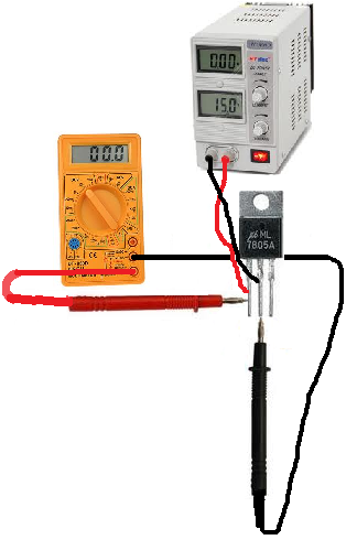
If we read a higher voltage, then the voltage regulator is receiving sufficient voltage to regulate down.
Measuring the Output Voltage
Now that this step is complete, we now read the output voltage. If the regulator is rated to output 5 volts, then we should read a voltage very near 5 volts coming out from its output. The LM7805 is a voltage regulator is rated to output 5 volts, so we should read this output.
To measure the output voltage, we place the same multimeter set in the DC voltage setting and now place
the positive probe of the multimeter on the output pin of the regulator and the negative probe on the ground pin of the regulator.
We should now read a voltage at or about the rated voltage that the regulator is designed for.
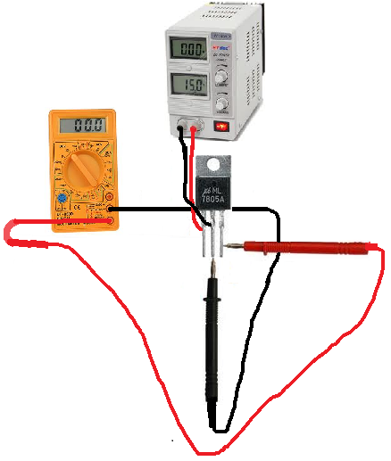
If the multimeter does read a voltage near its rated output voltage, the voltage regulator is functional and is good.
If we do not, then the voltage regulator is defective, as it does not do the job it was designed for, which is output a regulated voltage.
An adjustable regulator can be tested in the same way. Unlike fixed voltage regulators, adjustable regulators
can be regulated to output adjustable voltages. All a user must do is calculate the output that the regulator should output and perform
the same test as is shown above to see whether it is good or defective.
Related Resources
How to Connect a Voltage Regulator
How to Connect an Adjustable Voltage Regulator
How to Build a Zener Diode Voltage Regulator
How to Read a Digital Voltage in Circuitry