Low Pass Filter Calculator
RC Low Pass Filter (Passive)
This passive RC low pass filter calculator calculates the cutoff frequency point of the low pass filter,
based on the values of the resistor, R, and the capacitor, C,
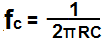
of the circuit, according to the formula fc= 1/(2πRC).
To use this calculator, all a user must do is enter any values into any of the 2 fields, and the calculator will calculate the third field.
This calculator allows a user to select the magnitude of the units of the capacitor, including picofarads (pF), nanofarads (nF), microfarads (µF), and farads (F),
as well as the unit for resistance and frequency. After 2 values are entered in, the user clicks the 'Calculate' button, and the result is
automatically computed. The resultant value of the
cutoff frequency calculated is in unit hertz (Hz) for frequency, farads and microfarads for the capacitor, and ohms(Ω) for the resistor.
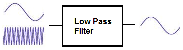
An RC low pass filter is a filter circuit, composed of a resistor and a capacitor, which passes low-frequency signals and
blocks high frequency signals. When a resistor is placed in series with the power source
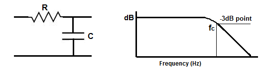
and a capacitor is placed in parallel to that same power source, as shown in the diagram circuit above, this type of circuit forms a low pass filter. It forms a low
pass filter because of the reactive properties of a capacitor. A capacitor is a
reactive device. This means that the resistance that it offers to a signal changes
depending on the frequency of the signal. Capacitors are reactive devices that offer very high resistance, or impedance, to low frequency signals. Conversely, they
offer lower resistance as the frequency of the signal increases. Thus, a capacitor offers very low impedance to a very high frequency signal. Because they offer
low impedance to high-frequency signals, high frequency signals normally go through, as they represent a low-impedance path. Remember that current always takes the path
of least resistance. So high-frequency signals normally take the capacitor path, while low-frequency signals don't; they go through to output.
When we calculate the cut-off frequency of the low pass filter, which is what this calculator does, we're calculating the point in the frequency response of the filter, where the gain has dropped by 3dB. Low pass filters pass low frequencies with high gain until it reaches a point in the frequency response curve where it no longer can pass out frequencies with as much gain. As the frequency gets higher, the signals get attenuated. The point at which the low pass filter can longer produce full gain and has dropped the gain by 3dB is referred to as the cutoff frequency. The cutoff frequency is the point where we know that the filter produces 0.7071V of the peak voltage gain. This is why it's crucial and why just knowing the cutoff frequency where the low-pass filter ends. At this frequency, signals begin attenuating greatly, and no longer pass signals with high very much gain.
As you can see in the above diagram, the low pass filter produces its full gain for low frequency signals and then begins producing lower gain signals.
At the cutoff frequency, there is a 3dB reduction in gain. And as the frequency increases, the gain reduces even more, until it's essentially 0.
RL Low Pass Filter (Passive)
This passive RL low pass filter calculator calculates the cutoff frequency point of the low pass filter,
based on the values of the resistor, R, and inductor, L,
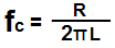
of the circuit, according to the formula fc= R/(2πL).
To use this calculator, all a user must do is enter any 2 values, and the calculator will compute the 3rd field. This calculator allows
a user to select the magnitude of the units of the inductor, including picohenry (pH), nanohenry (nH), microhenry (µH), and henry (H), as well as for the
units of the resistance and frequency. After 2 values, the user clicks the 'Calculate' button, and the result is automatically computed. The resultant value of the
cutoff frequency calculated is in unit hertz (Hz).
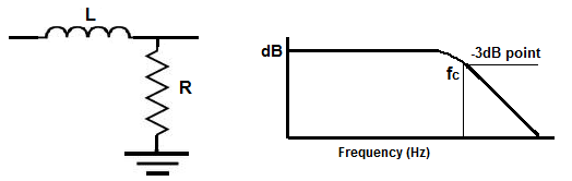
An RL low pass filter is a filter circuit, composed of a resistor and a capacitor, which passes low-frequency signals and
blocks high frequency signals. When an inductor is placed in series with the power source
and a resistor is placed in parallel to that same power source, as shown in the diagram circuit above, this type of circuit forms a low pass filter. It forms a low
pass filter because of the reactive properties of an inductor. An inductor is a
reactive device. This means that the resistance that it offers to a signal changes
depending on the frequency of the signal. Inductors are reactive devices that offer very high resistance, or impedance, to high frequency signals. Conversely, they
offer lower resistance as the frequency of the signal decreases. Thus, an inductor offers very low impedance to a very low frequency signal. Because they offer
low impedance to low frequency signals, low frequency signals go through, as they represent a low-impedance path. Remember that current always takes the path
of least resistance. So low-frequency signals normally take the inductor path, while high-frequency signals don't; they get impeded by the inductor's high impedance.
Just as with the RC filter, the RL low pass filter calculator calculates the cutoff frequency of the filter. This is the point in the frequency response of the circuit where the gain has reduced by 3dB. And as the frequency increases, signals attenuate more and more. The cutoff frequency calculation is important because it shows where the gain has been reduced 0.707V of the peak voltage. At this frequency, signals begin attenuating greatly, and no longer pass through with very much gain.
As you can see in the above diagram, the low pass filter produces its full gain for low frequency signals and then begins producing lower gain signals.
The cutoff frequency is the half power point, the point where the gain is now half of its full strength.
Inverting Op Amp Low Pass Filter (Active)
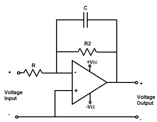
This calculator is for an active inverting op amp low pass filter.
This op amp low pass filter produces an amplified inverting signal at the output. This means that the output signal is
180 degrees out of phase with the input signal.
Resistor R and capacitor C form the cutoff frequency point.
Any frequencies below this frequency point will pass through to output amplified. Frequencies above this point will be greatly attenuated.
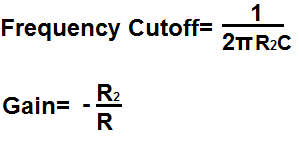
The formula for calculating the low cutoff frequency is, frequency= 1/2πR2C
The gain of the circuit is determined by resistor R2 and resistor R,
according to the formula, gain (AV)= -R2/R.
The negative sign means the output is the inverted signal of the input. This means whenver the input signal is ON, the output signal is OFF. They're exactly 180
degrees out of phase.
For this calculator, a user just has to enter the cutoff frequency
and the gain desired. The calculator will then compute the resistor R, capacitor, and resistor R2.
An important rule to keep in mind for this calculator if you are using a specific op amp is that you
have to consider the op amp's specification when building the circuit.
The 2 specifications of the op amp that must be considered are the maximum DC voltage that can be supplied to the power rails of the op amp and the slew rate of the op amp.
First, you must know the maximum DC voltage that the op ap can handle at the power pins. This will allow us to know the maximum voltage that the AC voltage can swing from peak to peak.
If, for example, the maximum DC voltage that the op amp can handle is ±18V, this means that the maximum AC voltage that the op amp can output is 36 volts peak to peak, or 18V peak. The
AC voltage can only go as high as the DC rail. So if we feed +18V into V+ and -18V into V-, the AC voltage can swing as high as +18V and as low as -18V, which is 36 volts peak to peak.
So the maximum DC voltage shows the maximum AC voltage it can show. If the AC voltage is larger than the DC rail, there will be clipping and distortion in the output signal.
The other factor is the op amp's slew rate. The op amp's slew rate is how fast the op amp can output voltage per a given unit of time. If the voltage is too large for a given
frequency, the op amp may not be able to keep up and it will produce distorted. The slew rate of the op amp allows you to calculate the amount of voltage the op amp can output for a given frequency.
Slew rates range widely from op amp to op amp. The LM741 op amp has a slew rate of 0.5V/μS. High-speed op amps can have slew rates up to 6000V/μS.
How you can calculate if the op amp can handle a certain voltage at a certain frequency is determined by the formula, slew rate= 2πfV. The best way to do it is to convert the
slew rate from volts per microsecond to volts per second. You do this by dividing the voltage by 0.000001 (a microsecond). Using the LM741's slew rate of 0.5V/μS, this would be 500,000V/s.
We then plug this into the slew rate formula, slew rate= 2πfV= 500,000= 2(3.14)f(10V)= 7961Hz. So the op amp can output 10V at a maximum frequency of 7961Hz. Any frequency above this at 10V
and the op amp won't be able to keep up with the output voltage. The frequency would be too fast for that voltage. Therefore, the op amp wouldn't be able to output that amplitude of voltage
at that speed (frequency). So the slew rate must definitely be considered when creating this circuit.
If you are using relatively high frequencies, you will need a high-speed op amp.
Noninverting Op Amp Low Pass Filter (Active)
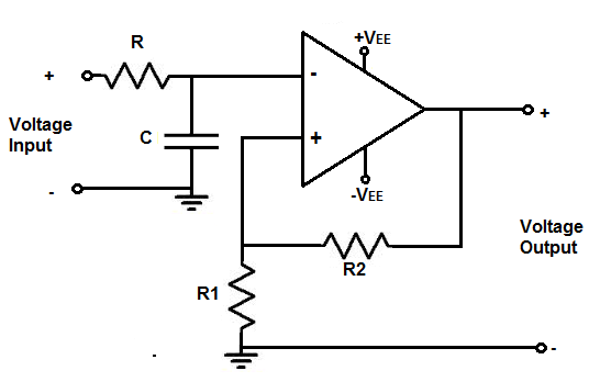
This calculator is for an active noninverting op amp low pass filter.
This op amp low pass filter produces a noninverting signal at the output. This means that the output signal is
exactly in phase with the input signal.
Resistor R and capacitor C set the cutoff frequency point.
Frequencies below this cutoff frequency get passed to output. Frequencies above this cutoff frequency point are greatly attenuated.
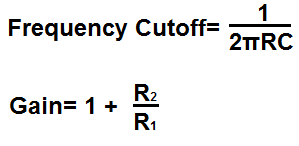
The formula for calculating the cutoff frequency is, frequency= 1/2πRC
The resistor R2 and resistor R1 determine the gain of the circuit. The gain of the circuit is determined
by the formula, gain (AV)= 1+ R2/R1.
For this calculator, a user just has to enter the cutoff frequency and the gain desired.
The calculator will then compute the resistor R, capacitor C, resistor R2, and resistor R1.
Just as with the other op amp filter circuit, the specifications of the op amp must be considered.
Related Resources
High Pass Filter Calculator
Bandpass Filter Calculator
Notch Filter Calculator
LC Resonance Calculator
Low Pass Filter
High Pass Filter
How to Build a Passive Bandpass Filter Circuit
How to Build an Active Bandpass Filter Circuit with an Op Amp
How to Build an Active Low Pass Filter Circuit with an Op Amp
How to Build an Active High Pass Filter Circuit with an Op Amp
