
Low Pass Filter- Explained
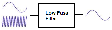
A low pass filter is a filter which passes low-frequency signals and blocks, or impedes, high-frequency signals.
In other words, low-frequency signals go through much easier and with less resistance and high-frequency signals have a much harder getting through, which is why it's a low pass filter.
Low pass filters can be constructed using resistors with either capacitors or inductors. A low pass filter composed of a resistor and a capacitor is called a low pass RC filter. And a low pass filter with a resistor and an inductor is called a low pass RL filter.
We will go through both of these type of circuits on this page and show how both RC and LC low pass filters
are constructed. Both circuits have the effect of passing through low frequency signals while impeding high-frequency ones.
Low Pass RC Filter
A Low pass RC filter, again, is a filter circuit composed of a resistor and capacitor which passes through low-frequency signals, while blocking high frequency signals.
To create a low pass RC filter, the resistor is placed in series to the input signal and the capacitor is placed in parallel to the input signal, such as shown in the circuit below:
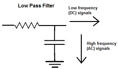
So, with this setup, the above circuit is a low pass filter. As a capacitor is a reactive
device, it offers differing resistance to signals of different
frequencies entering through it. A capacitor
is a reactive device which offers very high resistance to low-frequency or DC signals. And it offers low resistance to high-frequency signals.
As it offers very high resistance to
DC signals, in this circuit, it will block DC from entering and pass them off to an alternative part in the circuit, which is shown to the right by the arrow.
High-frequency signals will go through the capacitor, since the capacitor offers them a very low-resistance path. Remember that current always takes the path of least
resistance. Being that a capacitor represents a low resistance in a circuit for high-frequency signals, they will take the path through the capacitor, while
low-frequency
signals will take an alternative, lower-resistance path.
How to Build a Low Pass RC Filter
Now that we've gone through what a low pass RC filter is, let's go over a practical example of building one.
To build a low pass filter, the components we will use are a function generator, a 10nF ceramic capacitor, and a 1KΩ resistor.
This is the schematic of the circuit we will build, shown below:
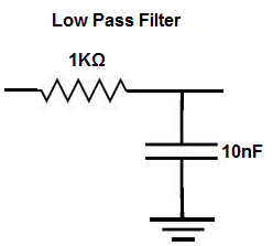
The formula to find the frequency cutoff point of an RC circuit is, frequency= 1/2πRC. Doing the math, with the values shown above, we get a frequency of, frequency= 1/2πRC = 1/2(3.14)(1KΩ)(10nF)= 15,923 Hz, which is approximately 15.9KHz.
This means that all frequencies above 15.9KHz are attenuated. And as you get further (higher) from the 15.9KHz region, the attenuation becomes greater and greater.
Frequencies below 15.9KHz are passed through without attenuation.
So if we input an AC signal into the circuit from the function generator and make the signal
a low frequency such as 10Hz, the circuit will pass this signal to output almost completely unattenuated. This is because low frequency
signals do not take the path of the capacitor.
You can
check this if you have an oscilloscope. If you now
increase the frequency of the signal to 30KHz, the signal will pass through to output with great attenuation. This is because high-frequency signals
go through the capacitor and not to
output, because capacitor is low resistance to them.
Low Pass RL Filter
A low pass RL filter, again, is a filter circuit composed of a resistor and inductor which passes through low-frequency signals, while blocking high-frequency signals.
To create a low pass RL filter, the inductor is placed in series with the input signal and the resistor is placed in parallel to the input signal, such as shown in the circuit below:
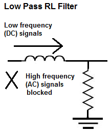
This circuit above is a low pass RL filter. How it works is based on the principle of
inductive reactance. Inductive reactance is how the impedance, or resistance, of the inductor changes based on the frequency of the signal passing
through the inductor.
Unlike a resistor, which is a nonreactive device, an inductor offers differing impedance values to signals of differing frequencies, just as capacitors do.
However, unlike capacitors, inductors offer very high
resistance to high-frequency signals and offers low resistance to low-frequency signals. So it's the opposite of a capacitor.
Therefore, the placement of the resistors are switched in RC and RL filter circuits.
So, based on this, the above RL circuit works effectively as a low pass filter.
It blocks high-frequency signals from entering and allows low-frequency signals to pass through unimpeded.
How to Build a Low Pass RL Filter
So, now that RL filters have been summarized, let's go over a practical example of building one.
To build a low pass filter, the components we will use are a function generator, a 470mH inductor, and a 10KΩ resistor.
This is the schematic of the circuit we will build, shown below:
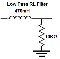
The formula to find the frequency cutoff point of an RL circuit is, frequency= R/2πL. Doing the math, with the values shown above, we get a frequency of, frequency= R/2πL = (10KΩ)/(2(3.14)(470mH))= 3,388 Hz, which is approximately 3.39KHz.
This means that all frequencies above 3.39KHz are attenuated. And as you get further (higher) from the 3.39KHz region, the attenuation becomes greater and greater.
Frequencies below 3.39KHz are passed through without attenuation.
So, again, you can check this on an oscilloscope to see that very low-frequency signals are passed through to output
unattenuated, while high-frequency signals undergo
attenuation.
To see how a low pass filter works in a real circuit, see the following video.
Below you can see a video of an RC low pass filter. This video demonstrates how the RC low pass
filter lets low-frequency signals pass through to
output with full gain, no attenuation, while greatly attenuating high-frequency signals.
Related Resources
Low Pass Filter Calculator
High Pass Filter
High Pass Filter Calculator
Filter Capacitor
Capacitor Charge (Charging) Calculator
Capacitor Impedance Calculator
How to Calculate the Current Through a Capacitor
How to Calculate the Voltage Across a Capacitor