
How to Build a Voltage Controlled Oscillator (VCO) with a 555 Timer Chip
In this circuit, we will show how we can build a voltage controlled oscillator (VCO) with a 555 timer chip.
A voltage controlled oscillator is an oscillator whose frequency is controlled by an input voltage.
Basically, the voltage input into the VCO chip controls how many times a digital signal will oscillate in a given time period.
We've already shown how to build a voltage-controlled oscillator with a 4046 phase-locked loop chip.
Now we will build a voltage-controlled oscillator with a 555 timer chip.
As output, a voltage-controlled oscillator produces digital square wave signals. Square wave signals are signals which can be in 1 of 2 states, either LOW or HIGH. The waveform alternates between HIGH and LOW, or 0 and 1, repeatedly.
This signal can be used for a variety of purposes, anywhere basically where a digital signal is needed. This includes clock signals, which are needed in a host of devices and chips. Chips which need clock signals include some digital potentiometers counters, microprocessors or microcontrollers, and many other types of devices.
A VCO is dynamic because we can vary the frequency of the digital signal just by changing the input voltage. So we can get a wide range of frequencies just by changing the voltage. So it's like a variable crystal oscillator.
We show how to build the circuit below.
Components Needed
- 555 Timer Chip
- 10KΩ Potentiometer
- 33KΩ resistor
- 10nF ceramic capacitor
- 100nF ceramic capacitor
The 555 timer can be obtained very cheaply from pretty much any electronic retailer.
The 555 timer can be obtained very cheaply from pretty much any electronic retailer.
The 555 timer is an 8-pin chip.
The pinout of the 555 timer is shown below.
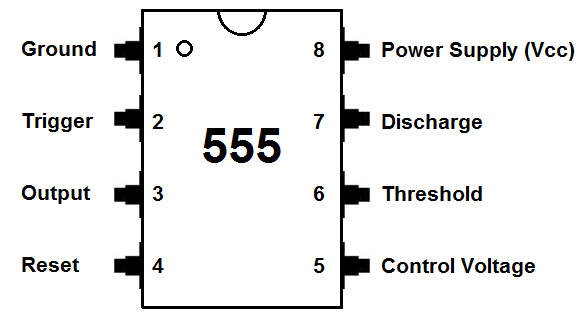
The 555 timer requires a power supply voltage of 4.5-16V. We connect this voltage to the VCC pin, pin 8, and we connect GND, pin 1, to ground.
The only other pins we use are the trigger pin, the output pin, the reset pin, and the threshold pin.
Pin 2 is the trigger pin. It works like a starter pistol to start the 555 timer running. The trigger is an active low trigger, which means that the timer starts when voltage on pin 2 drops to below 1/3 of the supply voltage. When the 555 is triggered via pin 2, the ouptut on pin 3 goes high.
Pin 3 is the output pin. 555 timer's output is digital in nature. It is either high or low. The output is either low, which is very close to 0V, or high, which is close to the supply voltage that's placed on pin 8. The output pin is where you would connect the load that you want the 555 timer to power. This may be an LED, for instance.
Pin 4 is the reset pin. This pin can be used to restart the 555 timer's timing operation. This is an active low input, just like the trigger input. Thus, pin 4 must be connected to the supply voltage of the 555 timer to operate. If it is momentarily grounded, the 555 timer's operation is interrupted and won't start again until it's triggered again via pin 2.
Pin 6 is the threshold pin. The purpose of this pin is to monitor the voltage across the capacitor that's discharged by pin 7. When this voltage reaches 2/3 of the supply voltage (VCC), the timing cycle ends, and the output on pin 3 goes low.
If you want to know all the pinout of the 555 timer in full depth, what each pin is and what each pin does, see 555 Timer Pinout.
In this circuit, we will connect the 555 timer to act as a voltage controlled oscillator.
The connections are shown below.
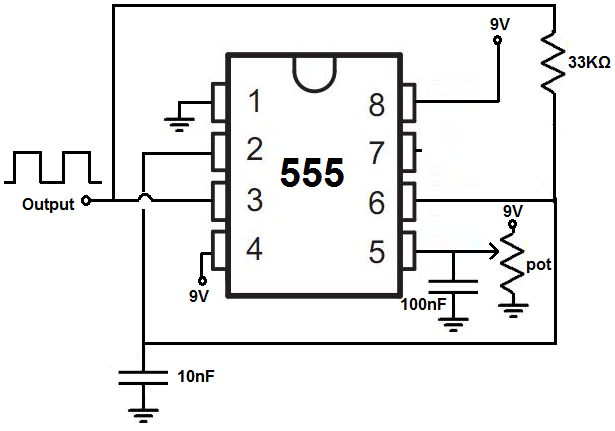
Voltage Controlled Oscillator (VCO) Using a 555 Timer
The voltage controlled oscillator (VCO) circuit that we will build using a 555 timer is shown below.
The breadboard schematic of the above circuit is shown below.
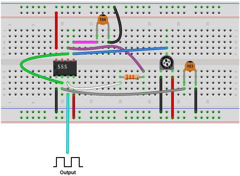
So we will now explain the workings of this circuit.
Pin 5 is the control voltage pin. To this pin, we connect a potentiometer to. One end of the potentiometer is connected to positive voltage and the other end is connected to ground. By varying the potentiometer resistance, we change the voltage input into this pin. The voltage can reach a maximum value of +9V when the potentiometer is turned all the way to one end where it offers full resistance. And the voltage reaches a minimum value of near 0V when the potentiometer is turned all the way to the other end where it offers near 0Ω of resistance.
You can do it this way. Another way you can do it is by simply connecting a DC power supply to pin 5 and adjusting the voltage. It doesn't really matter.
Either method you use you should connect a capacitor in parallel to this DC source of power. The capacitor serves to clean up noise from the DC power source so that the output square wave signal produced by the 555 timer isn't as noisy. A capacitor cleans up significant noise and makes the square wave more clean or pure.
This VCO offers a wide range of frequencies.
When the voltage is high, the frequency is low. As we decrease the voltage to the control voltage pin, the frequency increases.
Additionally, if you want to increase the frequency of the output signal, you can decrease either the resistor or capacitor in the RC network. So, for example, you can change the 33KΩ with a 10KΩ resistor. This will significantly increase the resistance. If you want to decrease the frequency of the signal, you can either increase the resistor or capacitor value in the RC network. So, for example, you can change the 33KΩ resistor to a 100KΩ resistor.
And this is how a voltage controlled oscillator works with a 555 timer chip.
To see how this circuit works in real life, please see the video below.
Related Resources
How to Build an LED Flasher Circuit with a 555 Timer Chip
How to Build a Clock Circuit with a 555 timer
How to Build a 555 Timer Delay Before Turn On Circuit
How to Build a 555 Timer Delay Before Turn Off Circuit
How to Build a Sine Wave Generator with a 555 Timer Chip