
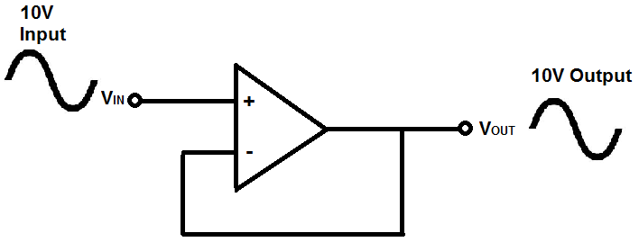
What is a Voltage Follower?

A voltage follower (also called a unity-gain amplifier, a buffer amplifier, and an isolation amplifier) is a op-amp circuit which has a voltage gain of 1.
This means that the op amp does not provide any amplification to the signal. The reason it is called a voltage
follower is because the output voltage directly follows the input voltage, meaning the output voltage is the same as the input
voltage. Thus, for example, if 10V goes into the op amp as input, 10V comes out as output. A voltage follower acts as a buffer, providing
no amplification or attenuation to the signal.
What is the Purpose of a Voltage Follower
One may ask then, what is the purpose of a voltage follower? Since it outputs the same signal it inputs, what is its purpose in a circuit? This will now be explained.
An op amp circuit is a circuit with a very high input impedance. This high input impedance is the reason voltage
followers are used. This will now be explained.
Voltage Followers Draw Very Little Current
When a circuit has a very high input impedance, very little current is drawn from the circuit. If you know ohm's law, you know that current, I=V/R. Thus, the greater the resistance, the less current is drawn from a power source. Thus, the power of the circuit isn't affected when current is feeding a high impedance load.
Let's look at both illustrations below:
The below circuit is a circuit in which a power source feeds a low-impedance load.
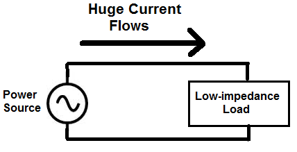
In this circuit above, the load demands and draws a huge amount of current, because the load is low impedance. According to ohm's law, again, current, I=V/R. If a load has very low resistance, it draws huge amounts of current. This causes huge amounts of power to be drawn from the power source and, because of this, causes high disturbances and use of the power source powering the load.
Now let's look at the circuit below, connected to an op-amp voltage follower:
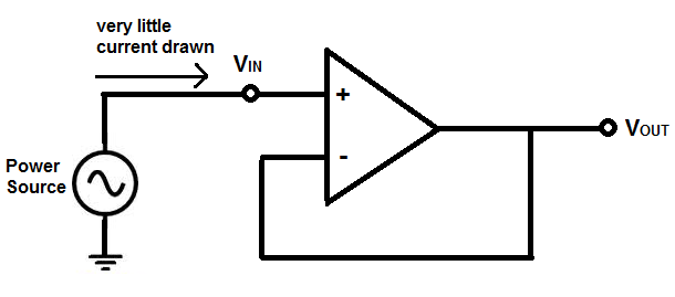
This circuit above now draws very little current from the power source above. Because the op amp has such high impedance, it draws very little current. And because an op amp that has no feedback resistors gives the same output, the circuit outputs the same signal that is fed in.
This is one of the reasons voltage followers are used. They draw very little current, not disturbing the
original circuit, and give the same voltage signal as output. They act as isolation buffers, isolating a circuit so that
the power of the circuit is disturbed very little.
Voltage Followers Are Important in Voltage Divider Circuits
So, current, as explained above, is one of the reasons voltage followers are used. They simply don't draw a lot of current, so they do not load down the power source.
Another reason voltage followers are used because of their importance in voltage divider circuits. This again deals with ohm's law. According to ohm's law, voltage= current x resistance (V=IR).
In a circuit, voltage divides up or is allocated according to the resistance or impedance of components.
Because an op amp has a very high input impedance, the majority of voltage will fall across it, (since it's so high impedance). So it's very valuable when used in a voltage divider circuit because strategically doing so can allow a designer to supply sufficient voltage to a load.
This will now be illustrated so you can see.
So let's say we have a circuit shown below which represents a voltage divider with a load attached to the output.
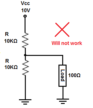
So the above circuit will not work and it will be explained now why not.
So in the circuit above, we have a voltage divider between the top 10KΩ resistor and the bottom 10KΩ and 100Ω resistors in parallel. So the voltage divider equation is characterized by the following equation, 10KΩ and 10KΩ||100Ω.
Doing the math across the 10KΩ and the 100Ω resistors in parallel gives us, 10KΩ || 100Ω = (10KΩ)(100Ω)/1.1KΩ= 99.01Ω ~ 99Ω.
So we next have a voltage divider between the 10KΩ resistor and the 99Ω resistor.
We now can use the voltage divider formula to see how much voltage will fall across the top 10KΩ resistor and the bottom 10KΩ resistor in parallel with the 100Ω resistor.
The voltage divider formula for the voltage across the top 10KΩ resistor is, V= 10V(10KΩ)/(10KΩ+99Ω)= 9.9V.
The voltage divider formula for the voltage across the bottom 10KΩ resistor and the 100Ω resistor is, V= 10V(99Ω)/(10,099Ω)= 0.098V or 98mV.
Remember, we use 99Ω because this is the equivalent resistance of the 2 resistors (the 10KΩ resistor and the 100Ω resistor in parallel).
Because the resistors are in parallel, they have the same voltage across each other, which is 98mV.
Now let's say the load needs about 5V to operate. You can see based on the calculation, there will not be sufficient voltage at the output. As we calculated, we had 98mV as our voltage across the load at the output.
The 100Ω resistance (load) carries down the resistance at the output too low. Therefore, in a voltage divider circuit, the load gets very low voltage, since voltage drops across loads in direct proportion to the resistance (V= IR).
However, if we take out the 100Ω load and instead connect an op amp instead (with its high input impedance), the resistance at the output (which ultimately powers the load) doesn't get drawn down. So the load can receive sufficient voltage.
Let's see how this circuit changes now with an op amp, with its high input impedance, and the load connected to the output of the op amp.
This is shown below.
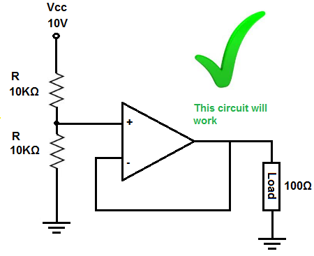
So this circuit above now works.
The voltage divider is now between the top 10KΩ resistor and the 10KΩ resistor and op amp at the bottom.
The op amp virtually offers infinite input impedance. Obviously, it's not really infinite in real life, but it is hundreds of megohms. Let's assume it's 100MΩ, though it can be much more.
So the equation that would characterize our voltage divider is between, 10KΩ and 10KΩ || 100MΩ.
Doing the math on the equivalent parallel resistance of the 10KΩ || 100MΩ resistance gives, (10KΩ)(100MΩ)/(10KΩ + 100MΩ)= 9999Ω ~ 10KΩ.
So we have, 10KΩ || 10KΩ.
Any voltage divider composed of the same 2 resistances gives half the voltage of the power supply. But just to show the math, we have the voltage divider formula, 10V * (10KΩ)/(10KΩ + 10KΩ)= 5V.
So 5 volts falls across the top 10KΩ resistor and 5V falls across the bottom 10KΩ resistor and the 100Ω.
Since the 100Ω and 10KΩ resistor are in parallel, they both receive the same 5V.
So you can see how the op amp allowed us to buffer the output of this circuit so that the load receives the voltage it needs.
So these are the 2 chief reasons we use voltage followers. We either don't want to load down the power supply and/or we want to buffer the output voltage from a circuit so that a load (especially a low-impedance one) can receive the voltage it needs.
So voltage followers are important to either isolate a circuit so
that it doesn't draw down power or buffer a low impedance load so that it receives sufficient voltage.
Related Resources
How to Read a Digital Voltage In Circuitry
Why Does an Op Amp Have High Input Impedance and Low Output
Impedance?