
Switching Power Supply Operation Modes
In this article, we are going to discuss various switching power supply operating modes.
These are different modes in which a switching power supply can operate.
Modes that exist include continuous conduction mode (CCM), boundary conduction mode (BCM) or critical conduction mode, discontinuous conduction mode (DCM) or Diode Emulation Mode, and Forced Continuous Conduction Mode (FCCM), or Forced Pulse-Width Modulation Mode (FPWM).
The most common mode is the continuous conduction mode.
Before, we delve into each individual mode, let's get some background first.
A switching power supply is a power supply that has a power signal that switches on and off, on and off.
The amount of time for which it is on and off each cycle must be the same. This is referred to as a steady state. This is a state in which every switching cycle is an exact replica of the previous cycle.
Switching power supplies utilize inductors.
Inductors work by charging up energy in the form of current when exposed to an input voltage and then discharging this voltage when disconnected from this input voltage source.
It is this cycle of charging and discharging of the inductor that creates the initial waveform of a switching power supply.
If we can create waveforrms where ΔION = ΔIOFF = ΔI, we have achieved a switching topology.
This would mean that every cycle has a waveform that charges and discharges for the same period of time.
Now when talking about the various modes that exist, realize that we have only stated that a valid switching topology is one where the time the current is charging is equal to the time the current is discharging. We never, however, mentioned the actual (absolute) value of the current at the start (and end) of every cycle.
There are, in fact, a number of possibilities when it comes to this.
We could have a switching topology steady state in which the current returns to zero (0) every cycle; this would be a discontinuous conduction mode.
However, if the current stays pegged at some non-zero value throughout the cycle, this is referred to as a continuous conduction mode.
As stated before, the continuous conduction mode is the most common mode of operation encountered in power conversion.
The boundary conduction mode is the mode where the very trough of the discharge signal reaches 0 but it bounces right off, meaning the signal does not keep a value of 0 for any reasonable period of time.
As you will see in the waveform, the boundary conduction mode is situated exactly between CCM and DCM. Therefore, this waveform can be viewed either as a CCM or DCM philosophically and it really doesn't matter.
The forced continuous conduction mode is a mode in which a synchronous FET allows the current to actually go negative, meaning there is reverse current flow, before the current then reverses again, going back in its original position.
Below we examine all of these waveforms, so that you get a visual understanding of how they look.
We start with the continuous conduction mode (CCM).
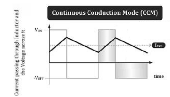
Again, this is a mode in which the current always starts and ends with a value above 0.
You can see that it starts at a positive current value, charges up as long as there is an input voltage source (VON), then once the inductor is disconnected from this input voltage source (VOFF period), it begins discharging but its lowest point is above a non-zero value. This then repeats over and over and over.
Next, let's look at the waveform for the boundary conduction mode (BCM) or critical conduction mode.
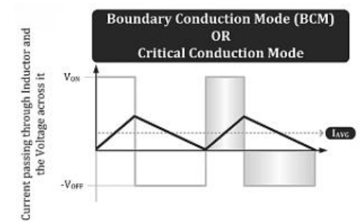
This again is the mode in which the waveform starts at 0 in the charging cycle and ends at 0 but does not stay there, just bouncing off of 0.
Next, we look at the discontinuous conduction mode.
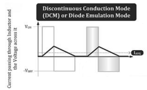
This mode is distinct because the waveform stays at 0 for a period of time before charging again.
During this period, when the inductor current is at 0, the catch diode in the circuit functions in reverse biased mode, blocking reverse current, preventing the inductor current from going negative.
Lastly, we look at the Forced Continuous Conduction Mode (FCCM).
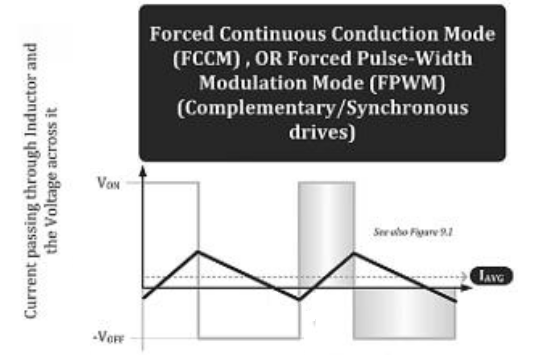
In this waveform, a synchronous FET turns on during the negative current period (reverse current), allowing the freewheeling current to flow through it in reverse direction, thereby allowing the inductor current to become negative (which is flow in the opposite direction).
It is fitting to note that for each of these waveform graphs, VON is the voltage across the inductor during the on-time and VOFF is the voltage across the inductor during the off-time.
Also note that the inductor current ramps up at a rate of VON/L and ramps down at a rate of VOFF/L. This is because the rate of change of inductor current is, dI/dt= V/L, originally derived from the equation, V= L(dI/dt)
Which of these operating modes actually occurs depends on the specific circuit and also the application conditions such as how much output power we are demanding and what input and output voltages are.
Related Resources